Skip to Content

author

Author: Zach Hoeken

Blinkyboard + China Pollution Data = Win

blinkyboard

My buddies Matt and Max have designed a sweet board called the Blinkyboard. It fits nicely into an addressable LED strip and allows you to easily control it. The board itself is Arduino compatible which makes working with this whole thing super easy.

I wanted to play around with it, but also make something useful. I live in Shenzhen, China where pollution can sometimes be an issue. Normally, I’ll check the aqicn.info site which has detailed pollution status for hundreds of cities in China. They have a gorgeous color-coded graph that I thought would be very nice if it was represented on an LED strip.

Songgang, Shenzhen AQI, PM2.5 Real-time Air Pollution Index

The Blinkyboard strip has individually controllable LED pixels, and the Air Quality site has a graph with a different color for each hour. I wrote a simple python script that takes the image, samples the color at each point, and then pushes that color to the LED strip. It was ridiculously easy to setup and the result was very nice. Now I have a simple, ambient, and colorful indication of what the pollution level is. The strip below is Beijing, which is much more polluted than Shenzhen, so the LED strip is a bit prettier, haha.

photo (56)

BotQueue v2: Slic3r Integration

BotQueue version 1 was a great proof of concept.  You could upload gcode files, and they would be distributed across multiple machines for printing.  It served that purpose well, and I received great feedback from the community as a result.  In particular, a major request was to integrate slicing into the BotQueue flow so that a user could upload an STL file directly.

BotQueue.com

Well, ask and ye shall receive!  Today I’m proud to announce that BotQueue now supports online slicing with Slic3r, the wonderful open source slicing tool.  With this release of BotQueue, we are supporting the latest version of Slic3r (0.9.8) although if there is interest, I could add support for previous versions of Slic3r as well.

Here’s a quick overview of how this process works:

  1. You upload an STL or OBJ file to BotQueue.com
  2. Bumblebee (the BotQueue client) downloads and slices the 3D model into GCode.
  3. Bumblebee uploads the GCode back to the site for re-use by your other printers w/ the same config.
  4. Bumblebee executes the GCode created by Slic3r.

Now, what if a slicing job goes wrong and Slic3r reports some errors?  This is where two wonderful open source projects come to save the day.  First, the wonderful Thingiview.js plugin by Tony Buser. Second, the most excellent GCode Viewer plugin by Joe Walnes. If there is a problem with the GCode parsing, BotQueue will take you to a page where you can view the model and the gcode output to verify if it is correct or not.  Both of these plugins require WebGL to function properly, so make sure you have the latest FireFox, Chrome, or Safari installed.

Verify Job - SnakePin_50mm.stl __ BotQueue.com

This latest feature has been designed with you in mind.  I know that everyone has their favorite slicing engine, and their own custom configuration file.  BotQueue makes it ridiculously easy to manage all that.  The new slicing functionality is based around the idea of SliceEngines and SliceConfigs.  A SliceEngine is something like Slicer-0.9.8 or Skeinforge-0050.  A SliceConfig is the unique settings that you decide for a SliceEngine.  You can have as many SliceConfigs as you like.

Each bot is configured to use a particular SliceConfig. When a bot grabs a new job, it will start the slicing process.  First, it looks to see if that particular model has been sliced with its assigned SliceEngine and SliceConfig.  If it finds that, it can skip the whole process and use the pre-sliced gcode.  If not, it will download the 3D model and slice config and then slice the model into GCode accordingly.  Once it finished the slicing, it will proceed to print the resulting gcode.

This is awesome in so many different ways.  Let me count them for you:

1. All you do is upload an STL and it will automatically get printed.  Configure your bots once and then FORGET ABOUT SLICING FOREVER.

2. You can have 1 slice profile tuned to each bot, and BotQueue will intelligently choose the right engine and config to use when slicing.  No more dealing with 4000 configs and remembering what is what.

3. If you change a config, you can “expire” previously sliced jobs.  No more stale GCode files laying around.

4. Online viewer for both the GCode and 3D model.  You don’t need to install any client software just to look at a print job.

Currently Supported Slicing Engines:

  • Slic3r-0.9.8
  • older versions of slic3r on request
  • Pull requests to add new slicers gladly accepted!

Important – Upgrading to v2

First, get Slic3r running. BotQueue is currently on 0.9.8 and we’ll be continually adding whatever the latest version is.  After that, you will need to upload your configuration(s) to BotQueue from the relevant slice engine page. You can export the config from within the Slic3r program. If you don’t have a config for Slic3r, then the default one is a good place to start.  You will use Slic3r to change any configuration options, or you can edit the config by hand online.

Second, edit your bots in the web interface and choose the appropriate slice engine and slice config for each bot.

Third, upgrade your BumbleBee installation to version 0.1.0.  Download the file, extract it, and then run it from the commandline like normal. You will need to copy over the config.json file from your old Bumblebee install.

Congratulations, you can now slice and print jobs through the internet.

Warning: The previous BumbleBee from v1 is now obsolete.  Do not use it again!  Delete the old folder!

Sweet Lighter Motorcycle

My friend Gaby posted some pictures she found on QQ of someone’s DIY conversion of 2 lighters into some cute little motorcycle models. Pretty awesome. It’s in Chinese, but here’s a link to the guys microblog.

photo (33)

photo (41)

photo (40)

photo (39)

photo (34)

photo (35)

photo (36)

photo (37)

photo (38)

Stencil8 Upd8: Tindie + Fixtureless Hack

If you’re in the UK and want to get a Stencil8 tooling block, Nick Johnson has a Tindie campaign going. Please note, this is not my campaign. Stencil8 is open source and this is an enterprising maker trying to provide access to others at cost.

photo (24)

I’ve been playing with different techniques lately, and I may have found an even easier/cheaper way to align your stencil with your PCB using the PCB itself as a fixture.

photo (26)

This technique has the advantage that you don’t need a tooling block. It also means you can use a frameless stencil which can be much cheaper. The downside is that the pins aren’t securely fastened and the stencil can wiggle around during application. I haven’t confirmed it, but I think that can be fixed by using tape to hold everything down while you apply the paste.

photo (25)

Meet a Shenzhen Maker: Mr. Chen

I’ve been living in Shenzhen for almost 2 years now, and I’m continually amazed by this city. The people here are creative, it has the best resources for building things you can find anywhere in the world, an amazing climate, and friendly people everywhere. This is the story of one particular Maker I’ve met in Shenzhen, Mr. Chen.

IMG_1225

In my ongoing obsession with digital fabrication and small volume manufacturing, I stumbled upon the Chinese SMT Pick and Place scene. It started with the TM-240A that I found on Taobao and through that I discovered www.diysmt. om and oursmt.com. It turns out there are a bunch of people building and using low-cost pick and place machines for actual production of real products. I had to find out more.

IMG_1193

I used my super-crappy chinese skills and posted in the diysmt forum to see if anyone was local to Shenzhen and could show me their machine. I got a couple responses, and Mr. Chen agreed to meet me and show me his operation. Always down for an adventure, I agreed and got his address. My assistant/translator and I hopped in a taxi and away we went.

We arrived in a neighborhood on the outskirts of Shenzhen – the type with small alleys separating dozens of dusty apartments with stray dogs running around and open-air grocery stores selling meat on hooks. If you’ve ever been to China an ventured off the beaten track, you’ll know exactly what its like.

IMG_1203

Entering into Mr. Chen’s place, you feel like you’re stepping into a whole new world. His apartment was immaculate, but signs of making were there if you know what to look for. Tucked away in one corner was the pick and place machine that I came to see. Next to it was a coffee table with boards ready to be populated, surrounded by tea cups.

IMG_1241

After a round of tea, he showed me the machine in operation. This $4000 pick and place machine was awesome to see. He had about 16 feeders and was populating entire boards in a single go. Between snapping pics and taking video, I asked him about what he does with it and why he needs gear like this.

It turns out, Mr. Chen was more interesting than his machine! You see, he’s managed to carve our a nice little niche for himself by designing and manufacturing his own electronics and then selling them at the infamous Huaqiangbei electronics market. He started about 7 years ago and has been building and selling various things during that whole time. Today he was making AVR ICE programmers, but tomorrow he might build controllers for the fans for his brothers small DC fan factory.

As we got to talking about making and DIY culture, I began to get a sense that this down-to-earth guy was someone who really understands the so-called Maker culture. He was very business savvy, and even had a slogan: 花小钱,赚大钱 which roughly means spend less and earn more. What he was describing was a lean operation where he had digital fabrication tools that allowed him to retool and switch around really quickly and efficiently. His house was doubling as his production floor so he had very little overhead. He also understood that he needed to find niche markets in order to remain competitive.

IMG_1220

His setup was slick and efficient: order pcbs + stencils from a fab, apply solder paste using a clever fixture, use the pick-n-place machine to get the parts on the board, reflow everything in his smt oven, and then hand-solder the connectors. The solder paste fixture itself was rather brilliant. The stencil itself was attached to a hinged lid. He took a sacrificial pcb, hand aligned it with the stencil, and then glued it in place. He then took 2 header pins and nailed them into a connector hole until just a small nub was sticking out. These pins then became the alignment pins for the pcb to apply solder to. Brilliant, cheap, and effective.

IMG_1243.JPG

I complimented him on his self reliance and was surprised by yet another twist that would be enough to turn any urban farm-loving hipster green with jealousy. In addition to running his own electronics manufacturing operation, Mr. Chen was growing organic vegetables, and raising chickens and pidgeons on the roof of his apartment! This guy was the picture of self reliance, and he had a relaxed attitude that told me immediately that he had carved out a cozy existence in his life with his wife, son, pidgeons, and electronics. Watching the flock of pidgeons flying freely through the sky on a sunny winter afternoon, it was easy to see why.

IMG_1236

All in all, it was a lovely afternoon and I feel like I’ve come closer to understanding the impenetrable culture of Shenzhen makers. To all the Mr. Chen’s of the world out there, and anyone else who pursues the goal of self-employment through making, I salute you!

IMG_1227

Industrial PID Temperature Controller Teardown

+ PID Temperature Controller Teardown

Last weekend, I went to the Guangzhou markets with my buddy Matt. There was lots of good stuff there, but one of the things that caught my eye were these PID temperature controller modules. Its the sort of industrial process control gear that is normally inaccessible to mortals. Fortunately for me, this was China, so I plunked down 80yuan and took one home with me.

photo (16)

+ Exterior

The unit is an elongated cube with interface on one side and terminals on the other. Its got a schematic silkscreened on one side to make hooking it up possible without a reference manual. Pretty snazzy.

photo (22)

+ Interior

Getting inside was pretty easy. The thing has tabs that you press and all the guts slide right out.

photo (20)

The first thing I noticed was that the interior is pretty much all PCB. There are 3 PCBs + the terminal block that are all soldered together for electrical and mechanical strength.

Elsewhere there 2 PCBs connecting. They designed pads onto each PCB where they needed to connect. Then someone simply bridged the pads with solder. Very clever. Not the strongest connection in the world, but it is certainly cheap and effective.

photo (19)

The interface board is interesting. Nothing too fancy here. A couple buttons, some LEDs, and some 7-segment displays. Nice and simple.

photo (21)

The board appears to be controlled by an Atmega and they kindly left the ICSP header exposed and labeled. Probably for their manufacturing process, but if I wanted to hack this device I could load my own firmware too.

photo (18)

+ Wiring it up

The controller is powered with AC wall current (110-230v) so I hacked up a power cable to control it. I took a thermocouple and a heater cartridge and taped them together with Kapton. I wired up my desktop bench supply to provide current to the heater.

photo (23)

Unfortunately my PID settings were way off and this thing has too many options that I didn’t want to mess with. After a couple minutes though it settled in an the appropriate temperature.

photo (17)

Challenges of Building a CNC Stepper Driver

I’m fascinated by motor drivers, and stepper motors in particular. There is just something so awesome about a modular little unit that will allow you to control a motor. As the motors get bigger, the awesomeness increases.

Lately I’ve been looking at high powered driver chips as part of a plan to build a CNC machine. Toshiba makes some great chips. The TB6560 is the ‘classic’ driver chip they make: 1/16th step, 4amps, and >30 volts. Unfortunately it has some flaws with power sequencing that causes it to blow up if you don’t turn VCC on before VMOT.

They’ve since released a few new driver chips. I designed a board around the beefy THB6064AH. This chip is pretty badass as its a 4.5A, 1/64th step, 50V beast. This thing will do some damage with the right motor. Unfortunately I’ve been struggling with the design. You can find it on Github.

Lately I’ve discovered an even more awesome chip! The THB7128. Not only is it cheaper than the THB6064AH, but it does 1/128th stepping. The internet doesn’t have a ton of info. This appears to be a new chip on the market. This should make for extremely smooth operation. The only real downside is that it maxes out at 3A instead of 4.5A. Most of my motors are <3A so that shouldn't be a problem. I've ordered a demo board to test it out.

With my new design in hand, I ordered the boards + a new test fixture and got cracking. I used my Stencil8 setup to make 6 beautiful prototypes and a test fixture to go with it. Then things started to go wrong.

The Ugly Details of How I Messed Up

First, I messed up the connector on the test fixture. Basically it was mirrored, so I had to solder on the headers on the back side. That just generally made things awkward. Always do a reality check before purchasing boards!!!! Your printer and some cardboard (or old pcbs) are your friends.

Second, I messed up a couple traces on the PCB. Nothing major, but things like the relay enable lines for 5V and VMOT being the same weren’t cool. Easy enough to fix with some jumper wires. The good news is the relays fired up first try, and the current measuring works as expected. I’ll do a writeup of this new and improved test fixture soon.

Third, and here’s where the trouble really started: I had no idea how to design for these higher power drivers. I knew about the sense resistors, and what value to make… but not what wattage. I knew they needed fast response diodes, but nothing more than that.

One very real problem I had was using too small of resistors. I never really quite grokked how to select current sense resistors for stepper motor drivers that need them. It’s actually very simple! Your driver is rated for a given current (say 4 amps). The datasheet will typically recommend a resistor value, as well as a formula for current based on a VREF. From that, it is easy to determine the ohm rating of your resistor (for the THB6064AH, its 0.22ohm). What they don’t say (and this is probably obvious to a real electrical engineer) is that the WATTAGE of the resistor can be calculated by W = I^2*R. In this case, 4*4*.22 = 3.2W. That pretty much rules out SMT resistors like I was using. Instead, you’ll need to use ceramic resistor. These resistors come in different sizes, but 5W is probably a safe bet. The next lowest is 3W which is less than the max required wattacge.

Fourth, and this is the main problem that I bashed my head into for 2 days in a row: The THB6064H is NOT THE SAME as the THB6064AH. I somehow purchased the THB6064H chips while designing for the THb6064AH. Of course this results in completely unpredictable operation that was so tantalizingly close that I *just knew* it had to be something in my circuit. Turns out, it was just me being an idiot.

Ultimately, this was a very frustrating but enlightening problem. I bashed my head at almost every single problem – both perceived and real. I did find some real issues, but the ultimate problem was one that I had completely overlooked. In the process I used the scope on just about every single pin, verified the test fixture, and just generally went over it with a fine toothed comb. I also learned a ton about the workings of the diode bridge, the current sense resistors, the resistors that control the oscillator, etc. I wish I had gotten it in one, but hey… thats life!

The Mystical Art of Cost Estimation

There are plenty of resources on hardware hacking, writing code, marketing, and even business development on the net. However, I think there is an elephant in room that nobody is talking about. How the heck do you figure out how much your product is going to cost?

If you are planning on launching a Kickstarter, or are hoping to do any sort of presales this is extremely critical to the success of your business. At HAXLR8R our mission in life is to help hardware startups navigate this rocky road towards success. To that end, I’ve attempted to condense all the knowledge I’ve gained over the years into a nice 2000 word blog post. Check it out and let me know what you think!

Stepper Motor Driver Test Fixture Design

These days I’m spending my time exploring the manufacturing landscape of Shenzhen in preparation for HAXLR8R 2013, future hardware startups, and just to grow my skills in general.

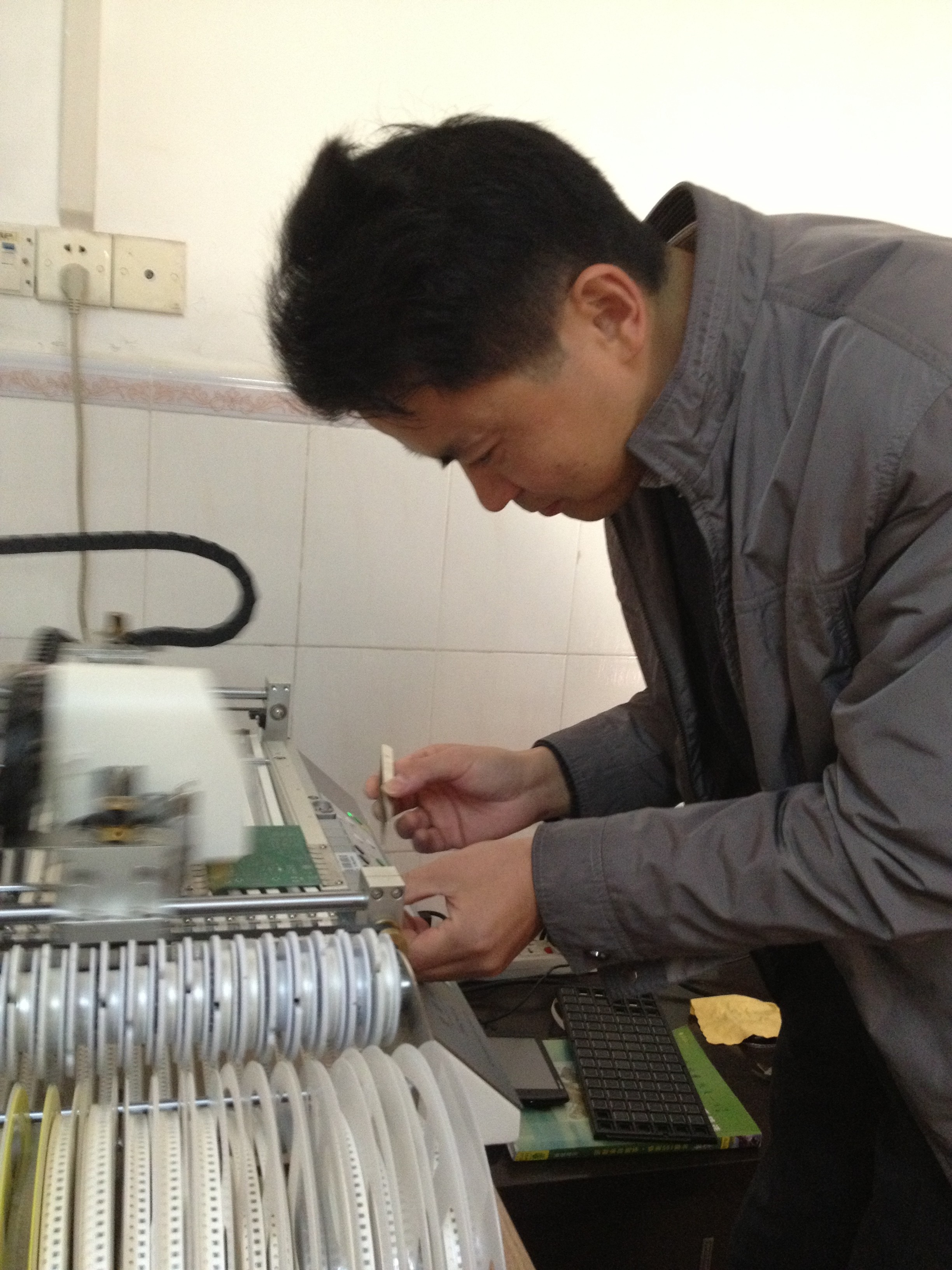
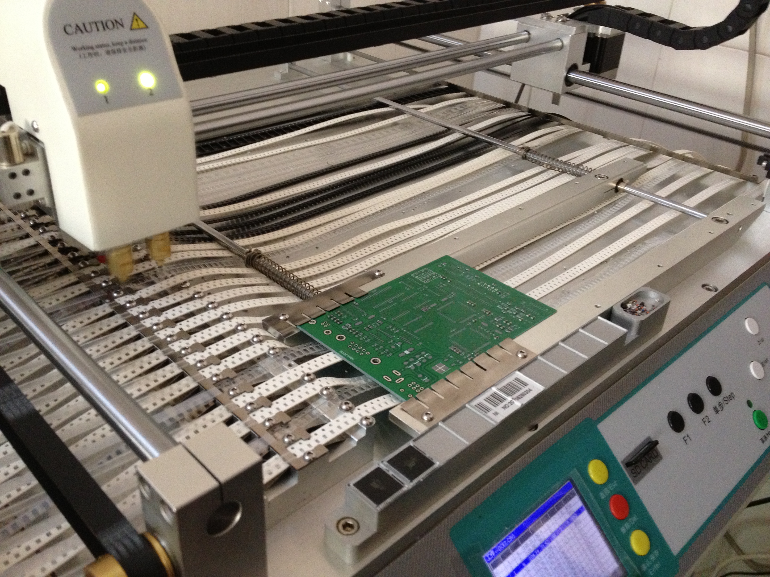
Motor drivers have been an ongoing passion in my life for a number of years, and I have a new design I’ve been working on based on the venerable Pololu driver. I’m getting 50 prototypes made by a local pcb assembly shop and I want to make sure they deliver quality prototypes. To that end, I’ve designed a test fixture to verify each board.

This sort of test is called a functional test, because it tests the actual functioning of the board as if it were being used in its intended application. For a motor driver, that means driving a motor and verifying that it did that correctly.

Design Goals

Here are a few of my design goals with the fixture:

  • Fully test each board in a simple and automated fashion.
  • Make the test fixture easy to use and easy to understand.
  • Document it so that others can learn from and expand on my work.
  • Release it open source (BSD) so others can use it to make better things.

Designing a test fixture is much different from designing a board for mass production. With a test fixture, I’m really not worried about component cost, PCB size, component density, certification, or any of those other worries that go into making electronics on a large scale.

Instead, what I care about is building a nice, reliable board that allows me to ensure the board I’m testing is doing what I expect it to be doing. The very first step towards achieving that is the spec! Realistically, you should write your spec before you even design the board you’re going to test. Of course this rarely happens in the real world, and the spec often changes during development as you come to better understand the nature of the components and the board you’re designing.

Test Specifications

At a minimum, your spec should have a listing of testable requirements. In the world of software, this are basically your unit test requirements. In electronics, you have things like current draw, voltage levels, etc. You probably also have application specific requirements that may require specialized sensors. In my case, I want to test a motor driver so I’m using a rotary encoder to record the exact movement generated by the motor. My spec looks something like this:

  • 1 rotation / Mode: full step / Direction: forward
  • 1 rotation / Mode: full step / Direction: reverse
  • 1 rotation / Mode: 1/2 step / Direction: forward
  • 1 rotation / Mode: 1/2 step / Direction: reverse
  • 1 rotation / Mode: 1/4 step / Direction: forward
  • 1 rotation / Mode: 1/4 step / Direction: reverse
  • 1 rotation / Mode: 1/16 step / Direction: forward
  • 1 rotation / Mode: 1/16 step / Direction: reverse

Test Fixture Controller

At the highest level, your test fixture has 4 states: idle, testing, pass, and fail. I am using 3 LEDs to indicate each state: yellow = testing, green = pass, and red = fail. I also have a 16×2 character LCD to provide more detailed feedback on sub-test status.

In order to drive all this, you need some sort of brains. I naturally went with the trusty and venerable Arduino MEGA. I could have used the smaller Arduino, but I wanted something that had pins to spare should I need them. Cost isn’t a huge consideration when designing a test fixture, so I wasn’t worried about overkill. Doing this the easy and fast way was a major consideration.

With my spec in hand, I fired up Eagle and started designing. The core of the fixture is pretty simple: an Arduino MEGA, 3 LEDs, a button to start the test, and some mounting holes. These are the core of the test fixture, and if you’d like to make your own, the design files are up on Github for your modification pleasure.

Beyond the core functionality, I added the motor driver socket, motor connection header, and the encoder connection header. It really is a rather simple test fixture.

The Arduino software is very straight forward: execute each test, display the right information at the right time, and light up the right LEDS. It also outputs extra data to the serial port which I could theoretically collect if I was going to do this on a massive scale and wanted to aggregate test result data. The software is also up on Github if you’re interested in seeing how it works.

The End Result

Once the board was designed, I soldered up the first prototype. Obviously it didn’t completely work. 😉 One major flaw was not connecting the VCC and GND for the LCD backlight. A couple jumper wires later and it was working like a charm.

Once I got it working, my main goal was to have a smooth and fast test sequence. For me that means each board should finish testing in under 10 seconds. It also means that it should be clear and easy to use. I believe I achieved that quite well, and if you watch the video you can see the test fixture in operation.

Making it tidy

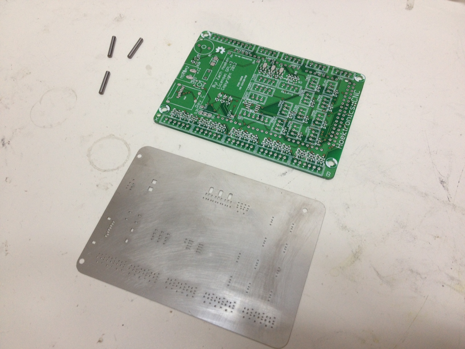
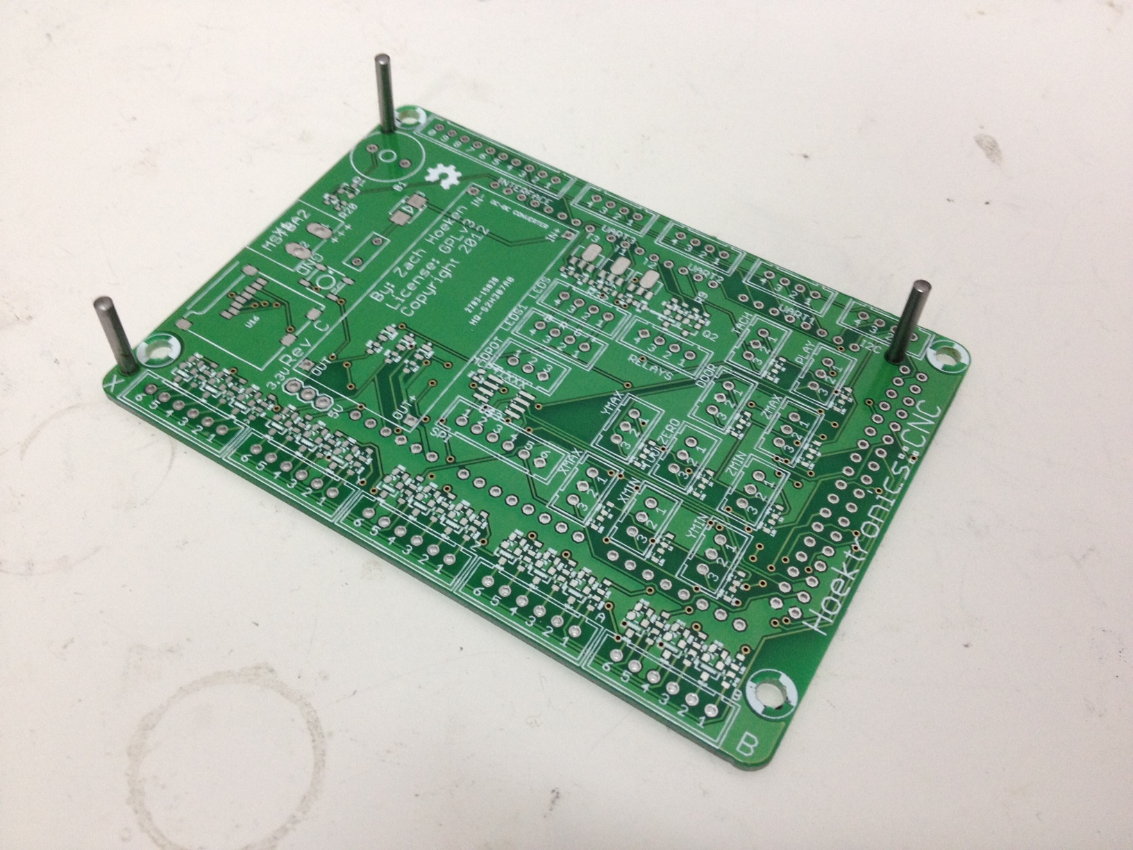
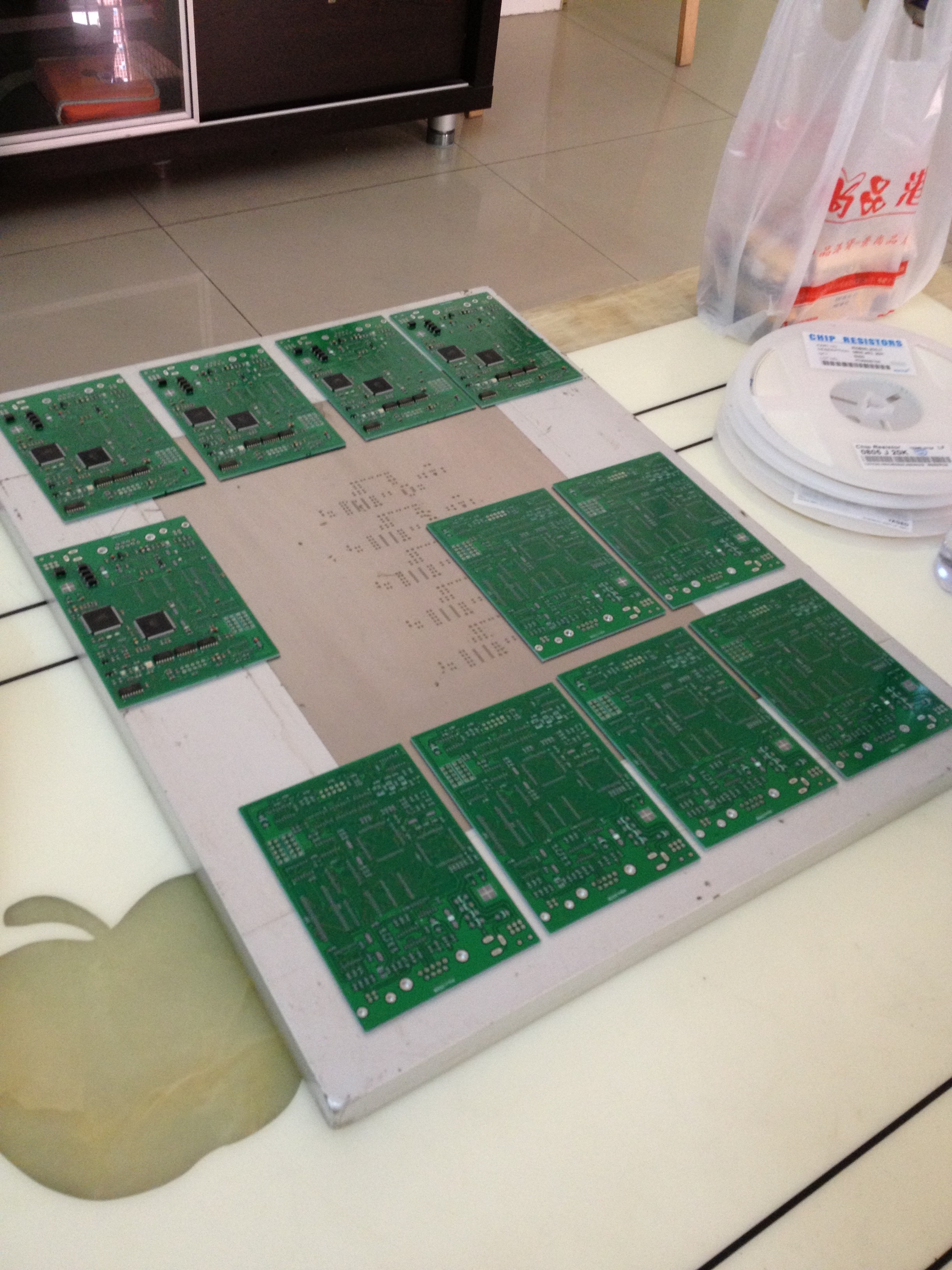
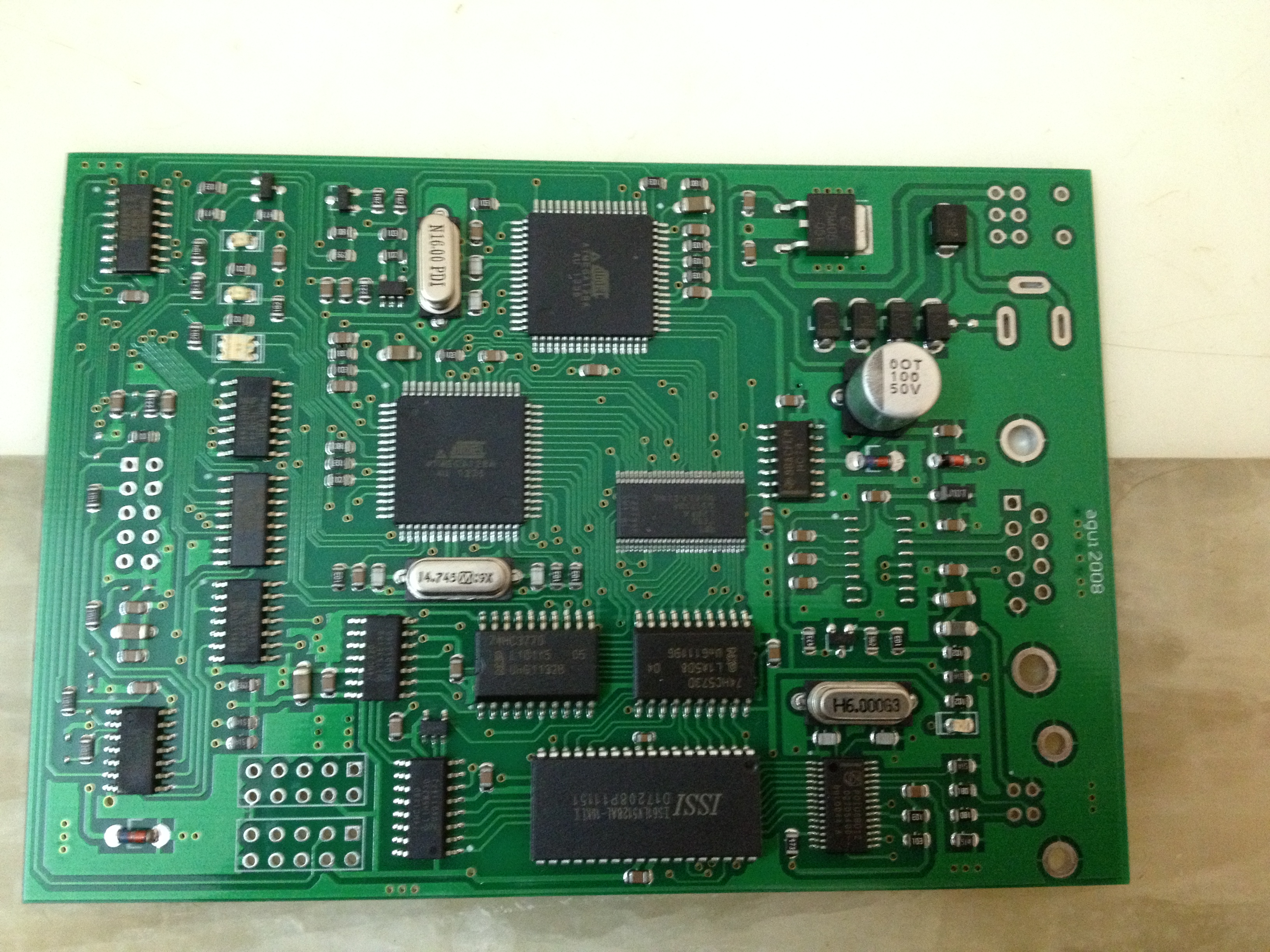
After building the test fixture, I realized it needed some sort of enclosure or structure. There are a couple ways to go about this. The first thing that crossed my mind was to use a custom laser-cut enclosure. It would look sweet and protect my new test fixture. However, I didn’t want to wait for my laser cutter supplier and I wanted something to keep it stable while I was working. Inspiration struck when I realized that I already had a very nice, digitally fabricated structure pre-made… the PCB itself!

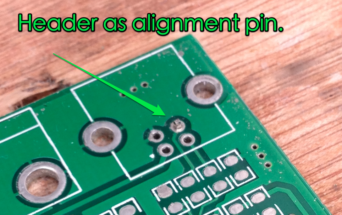
When you do a prototype run of a PCB, you typically get more than one. In this case, I got 12 PCBs even though I ordered the minimum number possible. I’m certainly not going to use all those PCBs, so I thought why not use them for the structure. Since the holes on the PCBs are exactly the same, all I had to do was add some standoffs between the PCBS and I had a nice, sturdy open-box frame that will probably stand up to moderate use.

Areas for improvement

All in all, I’m pretty happy with how this test fixture turned out. I used it to test my hand-made prototype boards, and it passed the working ones while failing the broken ones. I consider that in and of itself to be a success. However, this test fixture is very simple and there is lots of room for improvement! When I do a Rev B, here are some of the things I’d like to do:

  • Add current measurement to the VCC and VMOTOR power supplies. I want to know how much current is being drawn at various points during operation. For example when the board first starts up, I would like to be able to detect a short and turn it off. I would likely use something like the ACS712 chip.
  • Add relays to VCC and VMOTOR supplies. In combination with the current measurement chip, this would allow me to detect shorts. It would also build more safety into the device since plugging and unplugging the driver would happen with the power off.
  • Add a digipot to change the VREF settings. Right now this functionality is not begin tested, and its a pretty critical part of the board design. With the current measurement stuff added in, it should be pretty straightforward to verify it too.
  • Move the connectors to the bottom of the board to keep things tidy. I’d like all the wires to be on the inside of the test fixture if possible.
  • Move the stepper driver socket to the middle of the board. Right now it is a bit tucked away in with the other components. It makes routing a bit trickier, but it would really make it easier to use for the operator.
  • Move the 4th hole outside the Arduino. I made a mistake of putting one of the mounting holes over the Arduino. PCB space isn’t a huge premium, so I should have made the PCB bigger to accommodate it.
  • Use blue LED for “testing” mode. Just because it will look cooler. Also, the 10mm LED footprints I used have bad pin spacing. Oops.
  • I used through hole parts because I thought “Oh, I’m only doing 1 of these.” It turns out that makes things harder to source, especially since I really only have SMT components in my workshop. Thru-hole, not even once. =)
  • The board itself has one major flaw: it is not polarized! This means the board could be inserted backwards and damaged. This is a design flaw with the original Pololu design, and I haven’t yet figured out a way to route around it and still maintain compatibility. I’m not sure how to modify the test fixture to prevent this either. This will be solved the good old fashioned way: good instructions, operator training, and paying attention.

Open Source Hardware

In case you didn’t notice while reading the article, this board and software is 100% open source, under the BSD license. You can get it on Github. You’re welcome to use it in your own projects, and the BSD license means you don’t need to contribute back. This means you should have no problems using it in a corporate environment where you might want to keep your test fixtures secret. Why release it that way? Well, because I’m cool like that. 🙂

Top 8 Tools to Survive and Succeed in China

I’ve spent the past year and a half living in China without any prior experience speaking Mandarin.  It’s been a bit of a struggle, but its really not too hard.  Over at Haxlr8r.com, I’ve compiled a list of the top 8 tools I’ve used to get by and even learn a little bit on the way.  Even if you’re not planning on moving to China in the future, this list may be useful to you in some way.  Enjoy!