I’m fascinated by motor drivers, and stepper motors in particular. There is just something so awesome about a modular little unit that will allow you to control a motor. As the motors get bigger, the awesomeness increases.
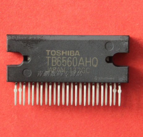
Lately I’ve been looking at high powered driver chips as part of a plan to build a CNC machine. Toshiba makes some great chips. The TB6560 is the ‘classic’ driver chip they make: 1/16th step, 4amps, and >30 volts. Unfortunately it has some flaws with power sequencing that causes it to blow up if you don’t turn VCC on before VMOT.
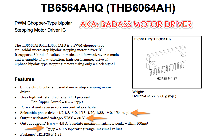
They’ve since released a few new driver chips. I designed a board around the beefy THB6064AH. This chip is pretty badass as its a 4.5A, 1/64th step, 50V beast. This thing will do some damage with the right motor. Unfortunately I’ve been struggling with the design. You can find it on Github.
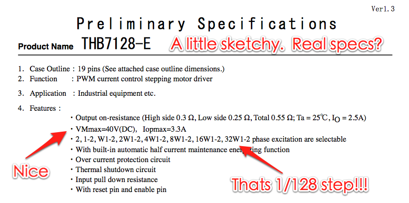
Lately I’ve discovered an even more awesome chip! The THB7128. Not only is it cheaper than the THB6064AH, but it does 1/128th stepping. The internet doesn’t have a ton of info. This appears to be a new chip on the market. This should make for extremely smooth operation. The only real downside is that it maxes out at 3A instead of 4.5A. Most of my motors are <3A so that shouldn't be a problem. I've ordered a demo board to test it out.
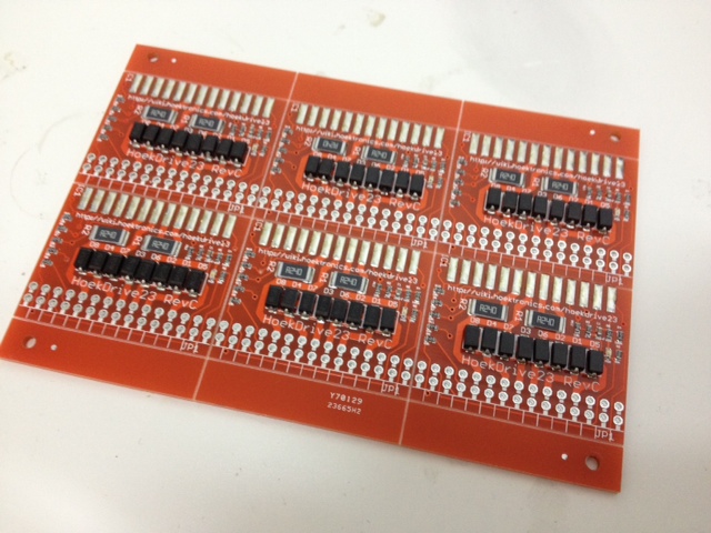
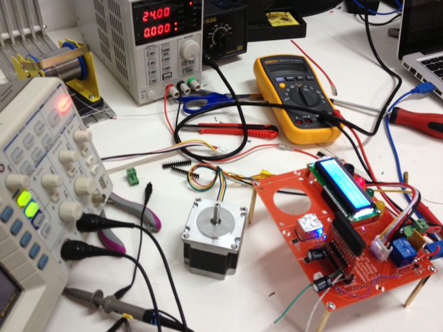
With my new design in hand, I ordered the boards + a new test fixture and got cracking. I used my Stencil8 setup to make 6 beautiful prototypes and a test fixture to go with it. Then things started to go wrong.
The Ugly Details of How I Messed Up
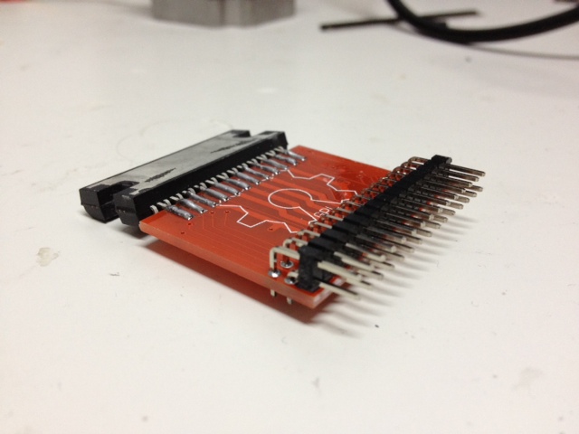
First, I messed up the connector on the test fixture. Basically it was mirrored, so I had to solder on the headers on the back side. That just generally made things awkward. Always do a reality check before purchasing boards!!!! Your printer and some cardboard (or old pcbs) are your friends.
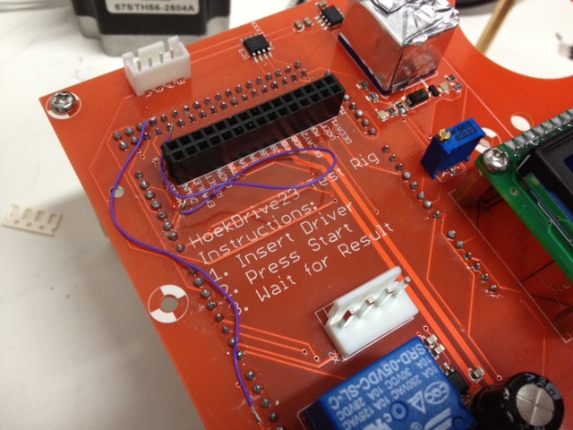
Second, I messed up a couple traces on the PCB. Nothing major, but things like the relay enable lines for 5V and VMOT being the same weren’t cool. Easy enough to fix with some jumper wires. The good news is the relays fired up first try, and the current measuring works as expected. I’ll do a writeup of this new and improved test fixture soon.
Third, and here’s where the trouble really started: I had no idea how to design for these higher power drivers. I knew about the sense resistors, and what value to make… but not what wattage. I knew they needed fast response diodes, but nothing more than that.
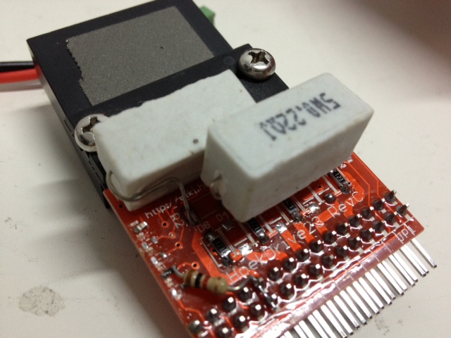
One very real problem I had was using too small of resistors. I never really quite grokked how to select current sense resistors for stepper motor drivers that need them. It’s actually very simple! Your driver is rated for a given current (say 4 amps). The datasheet will typically recommend a resistor value, as well as a formula for current based on a VREF. From that, it is easy to determine the ohm rating of your resistor (for the THB6064AH, its 0.22ohm). What they don’t say (and this is probably obvious to a real electrical engineer) is that the WATTAGE of the resistor can be calculated by W = I^2*R. In this case, 4*4*.22 = 3.2W. That pretty much rules out SMT resistors like I was using. Instead, you’ll need to use ceramic resistor. These resistors come in different sizes, but 5W is probably a safe bet. The next lowest is 3W which is less than the max required wattacge.
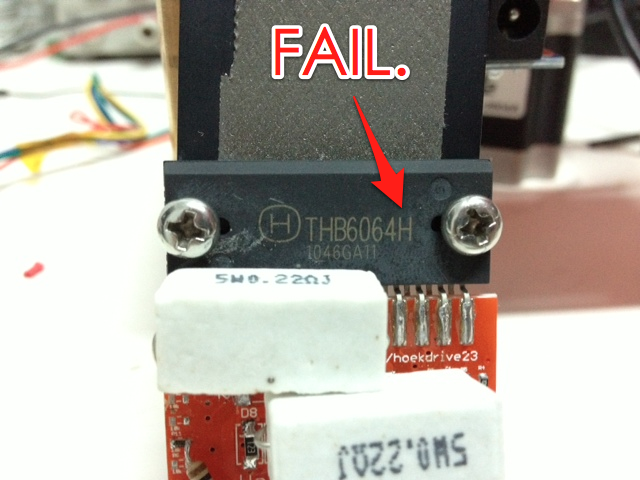
Fourth, and this is the main problem that I bashed my head into for 2 days in a row: The THB6064H is NOT THE SAME as the THB6064AH. I somehow purchased the THB6064H chips while designing for the THb6064AH. Of course this results in completely unpredictable operation that was so tantalizingly close that I *just knew* it had to be something in my circuit. Turns out, it was just me being an idiot.
Ultimately, this was a very frustrating but enlightening problem. I bashed my head at almost every single problem – both perceived and real. I did find some real issues, but the ultimate problem was one that I had completely overlooked. In the process I used the scope on just about every single pin, verified the test fixture, and just generally went over it with a fine toothed comb. I also learned a ton about the workings of the diode bridge, the current sense resistors, the resistors that control the oscillator, etc. I wish I had gotten it in one, but hey… thats life!
Zach, I’ve done that whole reversed PCB mistake before but mine a long time ago and was done with etch resistant tape which meant making a replacement was going to take a long time. I soldered the IC sockets on the copper side and then mounted the whole board on longer standoffs. Interestingly enough it was also for a stepper motor project.
Cheers,
Andy
oof. i can’t imagine doing this before era of cheap digital fabrication. hats off to you sir.
Thanks for being honest and sharing your story. I haven’t made any of my own boards yet, but I’ve messed up a ton of my electronic projects. I fried an arduino once new out of the box.
Nice job, I think your sense resistors are still overkill. If you are using a driver with a 3.5A rating like the TB6560AHQ, then you to set a current of 3A (leave some wiggle room so as to not run it at the exact limit of the part), you could use a sense resistor of 0.5V/3A = 0.166 ohm. At 3A, this will require a 1.5W resistor. A quick check on google reveals several suitable SMT resistors.
If you are happy with only 2A, then you could use a larger resistor and have a lower wattage resistor.
I’d suggest that you take a look at the Allegro stepper drivers, the A498x series of drivers. They are quite nice as well, and offer some interesting features such as allowing you to set the reference voltage instead of changing the current sense resistor to achieve different current limits.
Also, another tip I have learned from the TB6560 is to make sure you ground the heatsink. The thermal pad beneath the TB6560 should be grounded. I had a problem with a cheap chinese board from ebay that did not ground the heatsink and I believe caused one of my drivers to blow up (literally blasting open the ceramic package).
Thanks for the insights. It would be nice to get it nice, compact, and mostly SMT. I have worked with the Allegro chips… I made a pololu compatible one called HoekStep17 using the A4983. I just need more power Scotty!
Thanks for the insight into your project. Very interesting read. I’m planning to head into a similar one at some point in the future and I love hearing about successes and failures before I start mine. 🙂
Zach I am exited to see the results.
I am sure you will design the best
You didn’t mention it, but be wary of the inductance of current sense resistors. Since you’re chopping current on & off, unexpected inductance in some high-wattage resistors can wreak havoc in sensing circuitry.
There are special non-inductive current sense resistors available (including open-air).
definitely. i’m trying to be careful that the ceramic ones are non-inductive. i should smash one open to double check that its not coiled wires though. 🙂
Give it a go to the new Pololu DRV8825 driver. It’s fantastic, as it provides around dobule the current of A4988 ones in the same size (without a fan or a cooler).
Thats a nice chip, but it only does 2.5A peak. I really need something with >3A peak to drive the NEMA23 motors for a CNC. I’m a big fan of teh Allegro drivers tho… the A4983 is a champ for driving small NEMA17 motors.
For >3A i’ve found the cheapest way is to use a pre-built module like this one: http://www.osmtec.com/stepper_motor_driver_dm542.htm
but I am running CNCs with 2A, only thing is I am milling foam (using nema23 motors too): http://vimeo.com/52480287
Cool blog, man!
I love everything about high wattage resistors except for the price. What kind of costs are you looking at over in Shenzhen?
cheap. i think i paid 0.5kuai for a pack of 10. thats $0.10 or so.