Over the years, I’ve soldered a fair number of boards. I’ve also seen how professional factories produce their boards. This is my technique for doing it myself, and I hope it works as well for you as it does for me. 🙂
Note: the files needed to make the fixture, custom pcb setup, and stencil are on Github – Stencil8. This whole project is OSHW.
Required Tools Overview:
- PCB Fixture Block + Tooling Pins
- PCB w/ Tooling Holes
- Solder Paste Stencil
- Solder Paste + Squeegee
- Reflow Oven (or Hotplate)
- Isopropyl Alcohol (Rubbing alcohol.)
Process Overview:
- Set your tooling pins onto the appropriate grid points.
- Fit your PCB on the fixture.
- Place your solder stencil on the fixture.
- Use the Squeegee to apply solder paste to the stencil (and PCB).
- Gently remove the stencil from the figure.
- Use tweezers to place components on the appropriate pads.
- Reflow your PCB like normal using your reflow oven or hot plate.
- Solder your through-hole components (if any…)
- Test, test, test!
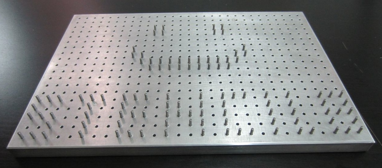
Key Component: Precision Tooling Fixture Block

First up, The pcb fixture block is the base of the whole technique (literally). It is a solid chunk of aluminum with precisely spaced 10mm grid of 2.5mm holes. These holes accept the 2.5mm tooling pins. These pins are what ensure that your board and stencil line up exactly. This precision is why this technique is so easy. It is a permanent tool, and you’ll only ever need one of these. Get a nice one, its worth it. You can DIY based on the drawings, or have one custom CNCed. I would highly recommend CNC.
Key Component: Solder paste stencil

Next, the solder paste stencil. This gorgeous digital craftwork is how you precisely control the amount and location of the solder onto your PCB. It is a thin sheet of steel that has tiny openings etched in it with acid or lasers. With this, you just glop on solder, and then scrape it off. When you’re done, you have a masterfully applied set of solder for every SMT component on your board. All you have to do is put things where they go.
Getting the solder stencil might be tricky. I live in Shenzhen, where a stencil like this costs $20. A google search for lasercut smt stencil shows that you can have it elsewhere, but its more expensive. Making the stencil is very easy: you just send the Solder Paste GERBER layers to the stencil manufacturer. In eagle these are the tCream and bCream layers respectively. They correspond to the .GTP and .GBP GERBER files.
Key Component: PCB with Tooling Holes

You have 2 options: put tooling holes into your PCB directly or have your board panelized w/ tooling holes on the margins. The latter allows you to do a large number of boards in a single application, which can be very nice in some situations. It also doesn’t affect the design of your board at all.
If you opt to put tooling holes into your PCB, you will need to make sure there is a corresponding circular pad in the solder paste layers in your CAD. This is because the solder paste stencil will need to have an opening there to fit the alignment pin. You can find a part for this in my EAGLE library.
If you have an excellent PCB supplier, they can send you your boards in a panelized state. This means you will get a single sheet of PCB that has all the boards + tooling holes. The PCB is “V-cut” so that you can easily break it apart by flexing the board. This is really awesome for doing small batches of boards. The document I used to communicate this to my Chinese PCB fab is located on github.
Key Tools: Solder Paste + Squeegee

In order to use this process, you need solder paste and a squeegee. The paste comes in tubs or tubes, although tubs are the most common. Try and mix it up a bit first before applying. You’ll want a squeegee with a metal blade in order to get the best application.
Key Tools: Reflow Oven

If you want to get fancy, use a reflow oven like this. This oven has temperature profiles which means it gradually heats up and cools down your PCB for optimum soldering. It’s also a nice “set it and forget it” type of process. If you’re forgetful like me, this means you can pop in the PCB and come back in half and hour without burning anything down.
If you don’t want to splurge, there is always the hotplate method which can be done for very cheap. Lots of tutorials out there.
Step 1: Set your tooling pins

The crux of this technique is using your precision tooling block + precision positioning pins to accurately align the PCB and the solder paste stencil. This helps you get very high quality solder paste deposition exactly where you want it. When you work with multiple boards, or when you work with very small parts it can be extremely difficult to align by hand.
Setting the pins is easy. Put the pins in the right spot, and double check it using your PCB. Technically you only need 2, but I’ve found that 4 gives you a nice, snug fit that helps with preventing misalignment.
Step 2: Fit your PCB on the fixture

Your PCB should fit over the tooling pins and lay flat against the tooling block. If it doesn’t fit, try using 3 or 2 pins. Snug is good, but don’t force it.
Step 3: Place your Solder Stencil on the tooling pins

Using the same tooling pins, place your solder stencil onto the tooling block. Since the stencil is much bigger, it can be hard to get it aligned. I like to line up one hole first using light from above, then rotate the stencil around that pin until it slides over the rest of the pins. It should lay flat against the PCB when you are done.
The pins should align the PCB and solder paste stencil very precisely. You should not see any green soldermask, only the silver pads where solder paste needs to be deposited.
Step 4: Apply your solder paste
Applying the solder paste is easy and fast. Place a dollop of solder paste onto the stencil. Use your squeegee to apply it across the face of the stencil. Angle the squeegee in the direction you’re moving it, and make sure to apply the paste both forwards and backwards to get every little nook and cranny filled.
Apply a dollop:

Squeegee it across:

Step 5: Gently remove the stencil from the fixture

Once you’ve applied the solder paste, carefully remove your stencil. You should immediately clean the stencil off with isopropyl (rubbing alcohol) so that you can use it again later. You should end up with beautifully applied solder paste like the picture above. I highly recommend leaving the PCB on the fixture. This will give you a stable base to work on, and will prevent you from knocking the PCB onto the floor or something like that.
Step 6: Place SMT components using tweezers

This is probably the trickiest part of the process. Use tweezers to pick and place each component onto the appropriate spot. A magnifying glass can help tremendously with this. Make sure you have good lighting and that you know what components go where. If you make a mistake you can dab a bit of solder on. Also, when the solder melts, it will self-correct to a small degree, so its okay if components are not exactly aligned. The boards in these pictures came out just fine, and you can see that the components are skewed a bit here and there.
Step 7: Reflow your board like usual

Use whatever process is convenient for you. I’m in love with this SMT oven here, but you may have your own preferred technique. If it works, go for it! Once the board has been soldered, it is a good idea to remove the flux using isopropyl alcohol and a toothbrush. Just don’t use it on your teeth afterwards!
Step 8: Solder your through-hole components (if any)

Using your trusty handheld soldering iron, solder in any through hole parts. If your board doesn’t have through hole parts, obviously skip this step.
Step 9: Test, test test!
Before using your board straightaway, test it! If you have a test fixture, then use that. If not, it is good to test for shorts between power/ground, as well as using a benchtop supply in current limiting mode set to a very low value and slowly ramp up the allowed current draw. If there is a short, this will allow you to catch it in a non-destructive way.
You’re done!
Using this technique you can solder very small parts that would otherwise be extremely difficult. I’ve successfully soldered 0402 components and QFN components with a 0.5mm pitch. You can easily do TQFP and any of the larger packages like 0603, 0805, and 1206.
If you have any feedback, leave it in the comments, or email me at zach at hoektronics dot com. Enjoy!


Recent Comments